Where Does the Current Really Flow in a Breadboard? (Beginners Always Miss This!)
Introduction
You just spent 30 minutes building your first circuit on a breadboard. You double-checked every connection. You followed the diagram exactly. But when you power it up, nothing happens.
Sound familiar?
Here’s the problem: where does the current travel in a breadboard isn’t as obvious as it looks. Those neat little holes hide a secret structure that beginners consistently misunderstand. One wrong assumption about current flow, and your circuit becomes an expensive paperweight.
This guide reveals exactly how current moves through your breadboard. You’ll discover the hidden metal strips that control everything, learn why that mysterious gap exists in the middle, and avoid the five mistakes that trip up 90% of beginners. By the end, you’ll trace current paths like a pro and build circuits that actually work the first time.
Let’s crack open the mystery of breadboard current flow.
What Is a Breadboard and Why Does Current Flow Matter?
A breadboard is a reusable platform for building electronic circuits without soldering. You push components into the holes, and internal metal strips create the electrical connections. Simple, right?
Not quite. Understanding where the current travels in a breadboard separates working circuits from frustrating failures. Current always takes specific paths through those internal strips, and if you place components in the wrong holes, electricity never reaches them.
Think of a breadboard like a road system. The holes are intersections, but not every intersection connects to every other one. Miss the right “road” for your current, and your signal goes nowhere.
The Basic Structure of a Breadboard
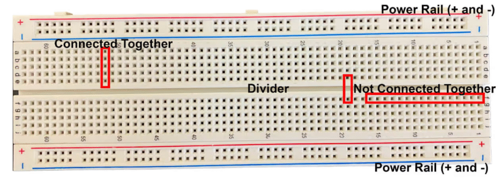
Breadboards come in various sizes, but they all share the same core design. The top shows a grid of holes, typically arranged in rows and columns. Underneath the plastic surface, metal strips connect specific groups of holes.
Most breadboards feature two main sections:
- Power rails running along the sides (marked with red and blue/black lines)
- Terminal strips in the center (arranged in lettered rows and numbered columns)
The terminal strips usually have 5 holes connected per group. The power rails have 25-50 holes connected in a single line. This configuration determines exactly how current flows through your circuit.
Why Understanding Current Flow Prevents Circuit Failures
When you don’t know where current travels in a breadboard, you make deadly assumptions. You might think two components connect when they’re actually isolated. Or you’ll short-circuit your power supply by accidentally bridging connections.
Real consequences include:
- Burned components from incorrect voltage paths
- Intermittent failures that seem random
- Hours wasted troubleshooting connections that were never made
- Damaged microcontrollers from reversed polarity
Professional engineers trace current paths before powering any circuit. This habit prevents 95% of breadboard problems before they start.
Where Does the Current Travel in a Breadboard? The Complete Answer
Here’s the truth: current flows through hidden metal strips that connect only specific holes. These strips run underneath the plastic surface where you can’t see them. Understanding their exact layout is critical.
The Hidden Metal Strips Inside Your Breadboard
Flip over a breadboard and peel back the adhesive backing (or look at a transparent breadboard). You’ll see thin metal strips running perpendicular to each row of holes. Each strip has small spring clips that grip your component leads.
In the terminal strips, current travels horizontally across 5 holes in the same row. If you insert a wire into hole A1, current can flow to holes B1, C1, D1, and E1. But it cannot flow to A2, A3, or any other row.
On the power rails, current travels vertically along 25-50 holes in the same column. Insert your power supply into the red rail anywhere, and every hole in that rail gets power. The same applies to the ground rail.
This layout means the current takes very specific paths through your breadboard. You must intentionally place components to create the circuit path you want.
Power Rails vs. Terminal Strips: Current Flow Explained
Power rails serve a different function than terminal strips. The rails distribute power and ground to multiple points in your circuit. The terminal strips create the actual circuit connections between components.
Power Rails:
- Run vertically along the sides
- Connect 25-50 holes in a continuous line
- Marked with red (+) and blue/black (-)
- Typically two rails per side (four total)
- Some breadboards have a break in the middle
Terminal Strips:
- Run horizontally in the center
- Connect 5 holes per row (letters A-E and F-J)
- Separated by the center gap
- Create node points for your circuit
When you need power for an IC chip, LED, or resistor, you run a jumper wire from the power rail to the appropriate row in the terminal strip. Current then flows from the rail, through the wire, into that row, and through your component.
The Gap in the Middle (Why It Exists)
Every standard breadboard has a gap running down the center, dividing the terminal strips into two sections. Rows A-E connect, but they’re isolated from rows F-J. This gap serves a critical purpose.
The gap exists for IC chips. Integrated circuits have pins on both sides that need to connect to different parts of your circuit. If the breadboard didn’t have this gap, inserting an IC would short-circuit the pins on opposite sides.
Here’s how current travels in a breadboard with an IC installed:
- The IC straddles the center gap
- Left-side pins (1-7) connect to rows A-E
- Right-side pins (8-14) connect to rows F-J
- Each pin gets its own row connection
- You wire components to the appropriate rows
This gap is your friend, but only if you remember it’s there. Trying to connect something across the gap without a wire is the #1 beginner mistake.
Common Mistakes Beginners Make About Breadboard Current Flow
Even experienced hobbyists occasionally mess up breadboard connections. These five errors account for most circuit failures:
- Assuming holes connect vertically in terminal strips. Current flows horizontally across rows, not vertically down columns. Placing two-component leads in the same column but different rows creates no connection.
- Forgetting the center gap. Trying to create a connection from row D to row F without a jumper wire fails every time. The gap blocks the current completely.
- Mixing up power rail continuity. Some breadboards have a break halfway down the power rails. If your power supply connects to the top half and your circuit is at the bottom, you’ll get no power.
- Creating accidental short circuits. Placing a wire that bridges the power and ground rails kills your power supply. This happens when you’re not tracking where the current travels in a breadboard carefully.
- Ignoring the direction of current-sensitive components. LEDs, diodes, and electrolytic capacitors have polarity. Even if you connect them to the right rows, reversed polarity prevents current flow (or destroys the component).
These mistakes share a common root: not visualizing the internal metal strips. Always picture those hidden connections before inserting anything.
How to Trace Current Flow in Your Breadboard Circuit
Professional circuit builders never guess about current paths. They trace them systematically using two reliable methods.
Step-by-Step Visual Method
This technique works without any tools. You simply follow the internal connections mentally or on paper:
Step 1: Identify your power source connection point. Note which power rail hole it occupies.
Step 2: Follow that power rail vertically. Every hole in that rail now has the same voltage.
Step 3: Find where jumper wires connect the power rail to the terminal strips. These wires carry current into specific rows.
Step 4: Trace horizontally across each row (5 holes). Any component lead in those 5 holes receives current.
Step 5: Follow component leads to their second hole. This creates the return path through the ground.
Step 6: Verify the ground path connects back to your ground rail, completing the circuit.
Draw this on paper for complex circuits. Use colored pencils for power (red), ground (black), and signal paths (other colors). This visual map reveals exactly where current travels in your breadboard before you apply power.
Using a Multimeter to Verify Current Path
A multimeter provides definitive proof of connectivity. Set it to continuity mode (the diode or sound symbol). This mode beeps when two points connect electrically.
Verification process:
- Power off your circuit completely
- Touch one probe to your starting hole
- Touch the other probe to the destination hole
- If it beeps, current can flow between those points
- No beep means no connection
Test every critical connection in your circuit. Verify power rail continuity, component lead connections, and ground paths. This takes 30 seconds and prevents hours of troubleshooting.
For current-limited applications, set your multimeter to current measurement mode. Place it in series with your circuit to measure actual current flow. This confirms not just connectivity, but how much current travels through each path.
Breadboard Current Flow: Real-World Examples
Theory makes sense until you’re staring at an actual circuit. These examples show exactly where current travels in a breadboard for common projects.
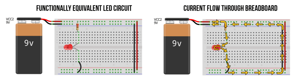
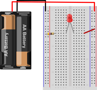
Simple LED Circuit Current Path
An LED circuit demonstrates basic breadboard current flow perfectly:
Components needed:
- 9V battery with a clip
- One red LED
- One 220Ω resistor
- Two jumper wires
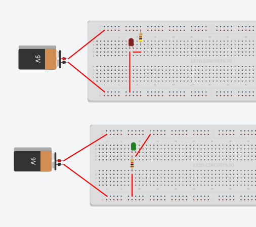
Current path breakdown:
The positive battery terminal connects to the red power rail through a wire. Current flows down that entire rail, making every hole positive. A jumper wire connects from the power rail to terminal strip row 10, holes A-E.
You insert the resistor with one lead in row 10 (let’s say hole C10) and the other lead in row 15 (hole C15). Current flows from the power rail, through the jumper into row 10, through the resistor to row 15.
The LED’s positive lead (longer leg) goes into row 15 (hole E15). Current flows through the LED. The negative lead goes into row 18 (hole E18). A jumper wire connects row 18 to the ground rail, completing the circuit back to the battery’s negative terminal.
Key insight: Current never jumps between rows automatically. You must physically connect each step with component leads or wires. The breadboard only provides connection points within each row.
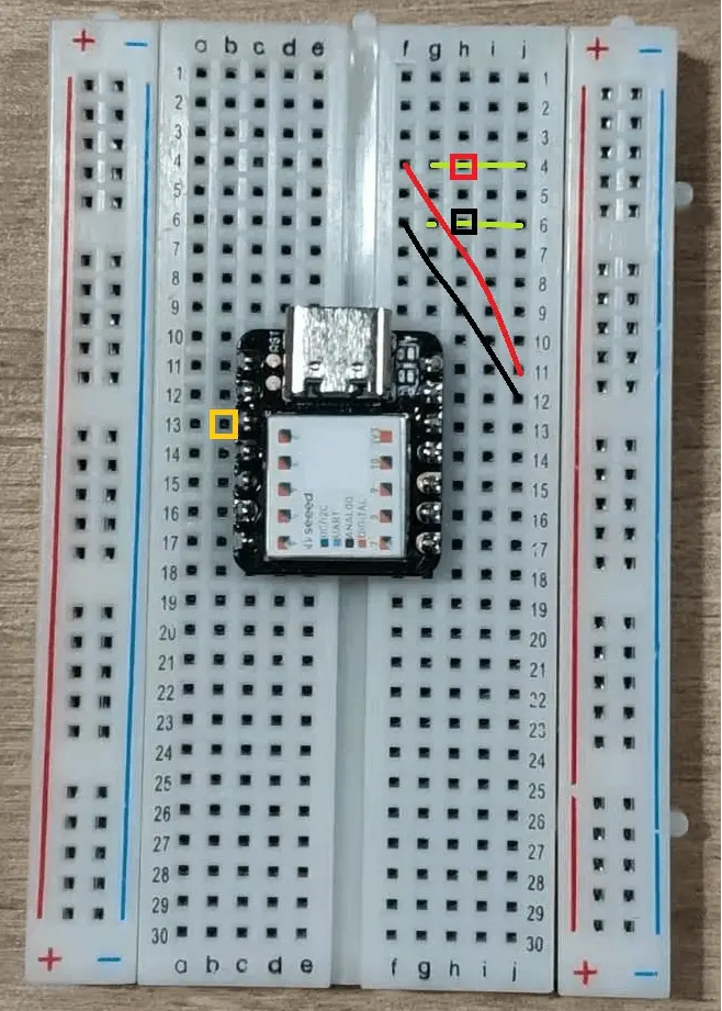
IC Chip Placement and Current Distribution
Integrated circuits reveal why the center gap matters. Consider a 555 timer chip:
The 555 has 8 pins. You place it straddling the center gap. Pins 1-4 go into rows F-J on one side, pins 5-8 go into rows A-E on the other side. Each pin occupies its own row number.
Current distribution:
- Pin 8 (power) gets a wire from the power rail to its row
- Pin 1 (ground) gets a wire from its row to the ground rail
- Other pins connect to resistors, capacitors, and output devices
- Each component connection requires a separate row
The beauty of this arrangement: current travels in a breadboard independently to each IC pin. Pin 3 (output) can drive an LED on rows A-E while pin 2 (trigger) receives input from a button on the opposite side in rows F-J.
Without the center gap, pins 1 and 8 would short together, destroying the chip instantly.
Advanced Tips: Maximizing Your Breadboard’s Current Capacity
Breadboards have physical limits. Understanding these constraints prevents damage and intermittent failures.
Current Rating Table
| Breadboard Component | Maximum Current | Voltage Limit | Notes |
|---|---|---|---|
| Individual hole contact | 1-2A | 5-15V | Varies by manufacturer |
| Metal strip (5-hole row) | 1-2A | 5-15V | Heat dissipation becomes critical above 1A |
| Power rail (full length) | 3-5A | 5-15V | Check for mid-rail breaks |
| Jumper wire (22 AWG) | 0.92A | 300V | Standard hookup wire rating |
| Jumper wire (24 AWG) | 0.577A | 300V | Common in jumper wire kits |
Important guidelines:
For circuits drawing over 500mA, use multiple power rail connections. Don’t rely on a single jumper from the rail to your circuit. Parallel connections distribute current and reduce heating.
Check your breadboard’s specifications. Cheap breadboards use thinner metal strips that overheat quickly. Quality brands like 3M and BusBoard use thicker contacts rated for higher currents.
Large motors, high-power LEDs, and voltage regulators under load exceed breadboard ratings. Use screw terminals or solder these components to a separate board. Connect to your breadboard only through low-current signal wires.
Contact Pressure and Resistance
Where current travels in a breadboard depends on good physical contact. The spring clips inside each hole must grip your component leads firmly. Poor contact creates resistance, causing voltage drops and heat.
Signs of bad contacts:
- The circuit works when you press down on the components
- Intermittent failures that come and go
- Warm or discolored plastic around holes
- Components that fall out easily
Solutions include cleaning holes with isopropyl alcohol, replacing worn breadboards after heavy use, and using proper wire gauges (22-24 AWG for solid core, not stranded).
Troubleshooting: When Current Doesn’t Flow Where You Expect
Your circuit should work, but it doesn’t. The power LED lights up, but nothing else happens. Here’s how to diagnose current flow problems systematically.
Loose Connections and Oxidation
Metal oxidizes over time, creating an insulating layer that blocks current. This happens faster in humid environments or when breadboards sit unused for months.
Symptoms:
- The circuit worked before, but now fails
- Wiggling wires makes it work temporarily
- Some rows work while others don’t
Testing process:
Remove all components. Insert a piece of solid 22 AWG wire into each hole in a suspected row. Push it in and out 5-10 times to scrape off oxidation. Apply a small amount of DeoxIT contact cleaner if available.
Test continuity across all 5 holes in each row. Any row that doesn’t show continuity has damaged contacts. Mark these rows and avoid them in future projects.
For power rails, test every 5th hole along the entire length. A break anywhere interrupts where current travels in a breadboard for that entire rail section.
Exceeding Current Limits
Pushing too much current through breadboard contacts causes permanent damage. The metal strips heat up, soften the plastic housing, and create gaps in the contact springs.
Warning signs:
- Plastic discoloration (brown or black marks)
- Melted appearance around certain holes
- Strange smell when the circuit operates
- Voltage measurements are lower than expected
Measure voltage at your power source, then at various points in your circuit. A significant voltage drop (more than 0.2V) indicates resistance from damaged contacts or undersized wires.
The fix: Rebuild the circuit using appropriate current-handling methods. Route high-current paths through thicker wires or external connections. Reserve breadboards for signal-level circuits and low-power experiments.
Key Takeaways: Mastering Breadboard Current Flow
Let’s lock in the critical concepts:
Core principles:
- Current flows only through connected holes via internal metal strips
- Terminal strips connect 5 holes horizontally per row
- Power rails connect 25-50 holes vertically per column
- The center gap isolates both sides of Ithe C chips
- No automatic connections exist between different rows
Practical skills:
- Always trace your current path before powering up
- Use a multimeter’s continuity mode to verify connections
- Watch for power rail breaks on larger breadboards
- Stay under 500mA for reliable breadboard operation
- Replace oxidized or damaged breadboards immediately
Mindset shift:
Stop assuming connections exist. Start proving they exist. This one change transforms you from a frustrated beginner into a confident circuit builder. Every professional engineer follows this practice, no matter how simple the circuit looks.
Understanding where current travels in a breadboard isn’t just technical knowledge. It’s the foundation for every successful electronics project. Master this, and you’ll spend less time troubleshooting and more time creating.
Conclusion: Build Circuits That Actually Work
You now understand the hidden world inside your breadboard. Those innocent-looking holes follow strict rules about where current travels in a breadboard. Five holes per row in terminal strips. Long vertical connections in power rails. Complete isolation across the center gap.
This knowledge transforms circuit building from guesswork into engineering. You can visualize current paths, predict connection problems before they happen, and debug failures in minutes instead of hours.
Apply these principles to your next project. Trace the current path on paper first. Verify critical connections with your multimeter. Build with confidence, knowing exactly how electricity moves through your circuit.
Your breadboard isn’t mysterious anymore. It’s a precise tool that follows predictable rules. Master those rules, and every circuit you build will work the first time.
Ready to put this knowledge to work? Grab your breadboard and follow the LED circuit guide to build the circuit. Trace the current path step by step. Feel how understanding current flow changes everything. Then tackle that project you’ve been postponing because “breadboards are confusing.”
They’re not confusing anymore. You’ve got this
FAQs About Breadboard Current Flow
Q: Does current flow through all holes in a breadboard?
No. Current only flows through holes connected by the internal metal strips. In terminal strips, 5 holes per row connect horizontally. In power rails, 25-50 holes connect vertically. Understanding where current travels in a breadboard means knowing these specific connections.
Q: Can I connect components vertically in the same column?
Only on power rails. In terminal strips, vertical holes in the same column are electrically isolated. You need a wire to connect different rows vertically.
Q: Why does my circuit work on one side of the breadboard but not the other?
Check for a break in your power rail. Many breadboards have a gap halfway down the rail. You need separate power connections for each section, or a jumper wire bridging the gap.
Q: How do I know if I’m exceeding my breadboard’s current capacity?
Measure the voltage at the power source and compare it to the voltage at your circuit. Drops greater than 0.2-0.3V indicate resistance from current limits. Also, check for warm plastic or components.
Q: Do breadboards work with AC?
Yes, but breadboards are designed for DC circuits below 15V. AC voltage creates additional stress on contacts. For AC projects, use terminal blocks designed for that purpose.
Q: Can I make permanent circuits on a breadboard?
Breadboards are prototyping tools. Vibration, humidity, and contact oxidation make them unreliable for permanent installations. Transfer working circuits to perfboard, PCBs, or use solderable breadboards.
Q: What’s the difference between solderless and solderable breadboards?
Solderless breadboards use spring clips for temporary connections. Solderable breadboards have the same hole pattern but require soldering, making connections permanent. Both follow the same rules for where current travels in a breadboard.

Hi, I am Raghav Ahuja a curious explorer, travel enthusiast, and the voice behind Travel The World Today. I believe in discovering the beauty of every destination without breaking the bank. Through my journeys, I share tips, stories, and travel guides to help you explore the world on a budget. Whether you’re a solo adventurer, a family traveler, or just planning your next escape, I’m here to inspire and guide you every step of the way.


Post Comment